Transformer: Advanced diagnostics
The transformer technical life is largely determined by the insulating system condition, and in particular by the High-Voltage paper-oil insulation. A long exposure of cellulose to a high temperature results in degradation of its mechanical properties, and specifically elasticity. An initial compression of the winding gradually disappears, and the winding becomes vulnerable to mechanical displacements by dynamic forces of the short-circuit current. Network transformers are exposed to several short-circuits in their technical life, and the current may attain 20 and sometimes even 40 times the rated current. The dynamic force acting on the winding is proportional to the current square, and in the case of older transformers such force may deform, or displace coils that are not kept together by the initial compression. Mechanical shocks caused by rail transport may also result in displacement of the transformer windings. This does not always result in an immediate breakdown of transformer insulation, and the damaged unit may still operate for some time. However, the reduced oil gaps between winding sections, and crushing of the brittle paper wrapped around the conductor reduce the dielectric strength of the oil channels. A next switching or atmospheric overvoltage may the break the weakened insulation, and initiate an in-service failure that may lead to fire and destruction of the transformer.
A periodical assessment of the transformer technical condition shall include the detection of winding displacement, as an important factor that complements the basic test for dissolved gas in oil, cellulose ageing and water content.
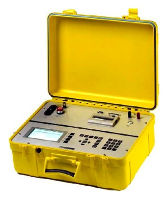
Energo-Complex has gained experience in recording and analyzing the winding frequency response (FRA) on several network and generator step-up transformers. The winding frequency response can be recorded in several test-circuit configurations using the specialized instrument TRAFTEK. These records are compared between the neighbor phase-windings, and between twin-transformers to draw conclusions and to formulate recommendations as to the further operation or repairs.
Solid insulation tests in service
Time of operation at a high temperature and moisture content in cellulose are the basic factors that decide on degradation of transformer solid insulation. Technical life of cellulose insulation is reduced by high moisture content that accelerates ageing process. An accurate assessment of water content in cellulose, as well as its degree of polymerization (DP) that is an indicative of ageing are of practical interests to the users, but there is no direct way of measure these values. Traditional method consists in taking measurement of the dielectric loss factor tg δ at power frequency of the transformer insulation in substation, taking oil sample and measurement of water dissolved in oil, and taking samples of paper insulation for laboratory tests. Unfortunately, all these methods are of limited accuracy. Besides, they require skilled and experienced personnel to take the samples and measurements and to interpret the readings.
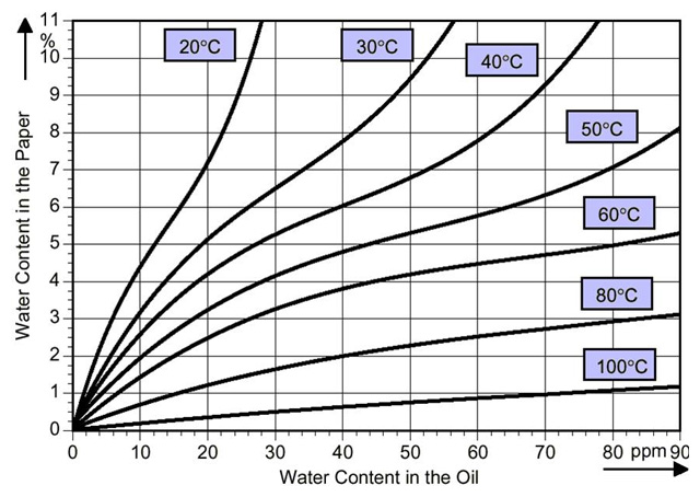
For instance, the water content in oil is measured in part per million (ppm) whereas in cellulose is expressed in percents (%). A relation between these two values has been determined and is given in form of graphs with temperature as a factor. Such graph is applicable in the thermal steady state when the paper and oil temperature is the same. This condition seldom applies to a transformer in service that is practically always in a dynamic state. Dissolved water keeps migrating from oil to paper, or vice versa, depending on the temperature of solid and liquid insulation.
Water content in cellulose may be evaluated from the water content in an oil sample examined in the laboratory, if the sample was taken at the top-oil temperature higher than 40oC, after an extended period of stable load and constant ambient temperature.
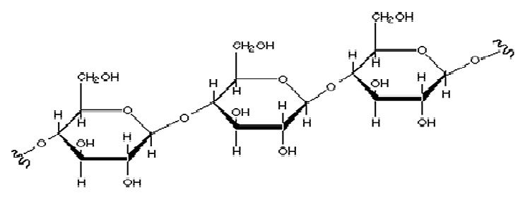
Cellulose structure
Cellulose fibers are composed of chain-forming molecules. Ageing breaks links between these molecules, and reduces length of cellulose fibers. Aged cellulose becomes brittle and looses its tensile strength. Cellulose reaches end of its technical life when its tensile strength is reduced by half.
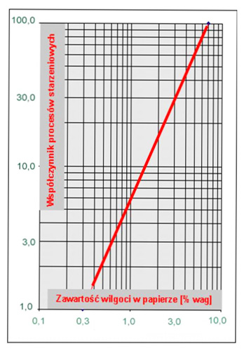
High operating temperature and water content reduce the technical life of cellulose insulation. Its remaining technical life is reduced by half if the temperature increases by 6oC to 8oC.
Assuming 0.5% moisture content in cellulose its technical life can be assessed at 500 years if the operating temperature is 80oC, but is reduced to 50 years at 100oC, to 6 years at 120oC, and to 1 year at 140oC.
Doubling the moisture content reduces the insulation life by half at a given operating temperature. Breaking cellulose molecule-chains produces water, gases: H2, CO, CO2 and furans, mainly 2FAL. Analysis of gas dissolved in oil, and of furans allows assessing the insulation condition and its remaining life.
Insulation dielectric-loss factor tgδ
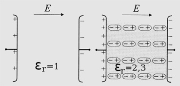
Capacitive current ic in a capacitor leads the applied an alternating voltage by 90o. This current increases with an increasing dielectric constant ε of the insulation, and with the applied voltage frequency f. A small current ir due to the dielectric loss of the insulation flows in phase with the voltage, and the dielectric loss factor tgδ has been defined as the ratio of these two components of the total current tgδ=ir/ic.
Alternating voltage applied to the dielectric periodically re-polarizes its molecules. However, the molecules can re-polarize up their relaxation frequency, beyond which they become inactive and the insulation dielectric constant is reduced. The dielectric loss caused by molecule re-polarization attains maximum at this relaxation frequency.
Frequency characteristic of ε and tgδ reveal this relaxation frequency of different molecules contained in the examined insulation. Water has a very high dielectric constant (εH2O≈80) but the relaxation frequency is rather low in the order of mHz (milihertz). Reference frequency characteristics of tgδ and ε have been developed using data obtained on models of artificially aged Transformerboard® and paper, as well as controlled moisture content in the models. Condition of an examined transformer-insulation can be assessed by comparison of the recorded tgδ and ε frequency characteristics to the reference curves.
Recovery Voltage Measurements (RVM)
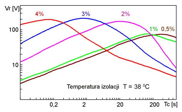
Transformer insulation is composed of oil ducts, cellulose barriers and wrapped paper layers. Each material is characterized by its dielectric constant ε and conductivity ρ. When a direct voltage is applied to the transformer insulation, an initial voltage distribution on oil, Transformerboard® and paper layers depends on their respective ε. However, the steady-state, or final voltage distribution is dictated by the respective ρ values. In consequence, an electric charge is accumulated on capacitance of the dielectric layer, and is subsequently dissipated by its leakage resistance. This results in a current impulse characterized by the time-constant proportional to the ratio of ε/ρ of the dielectric involved in the charge accumulation and dissipation process. The longest time-constant is attributed to water molecules, and an analysis of the leakage current impulse-form reveals water content in the dielectric. An instrument for determination of moisture content in transformer insulation was developed using this concept. A direct voltage charges the examined winding capacitance for the time T, then the winding is short-circuited to ground for the time T/2 to dissipate the charge accumulated on the geometric capacitance. This is the capacitance that would have been measured if there were no solid or liquid dielectric between the winding and grounded parts of the transformer. Subsequently, the short-circuit is removed, and a polarization recovery voltage is recorded on the winding capacitance. Then the highest value Vr of this voltage is plotted against the charging time T. Such plot reveals water content in the examined transformer insulation, and a skilled operator can assess age of the cellulose insulation.
An assessment of the transformer insulation condition is derived from measurements taken with a few complementary methods based on the insulation dielectric-polarization characteristics. Obtained results are compared to the conclusion drawn from the conventional chemical analysis of oil samples, and measurement of gas dissolved in oil.
Furan analysis is also performed when the insulation condition indicates the need of such tests. Our experts dress the list of necessary tests and measurements, according to the history of transformer operation, and in particular in-service failures and repairs.
Detection and evaluation of winding displacement
An early detection of displaced or deformed winding may prevent an in-service failure of the transformer, and allows the asset manager to plan the repairs in such a way to ensure the best use of available resources.
Conventional measurement of the winding short-circuit reactance have been effective in the case of major winding displacements, in particular radial buckling of coils. However, the local deformations cannot be always detected since of the winding reactance measured the power frequency is mainly affected by a change of the whole winding geometry.
To reveal the deformation of a few turns, or a single coil, the winding impedance has to be measured over a broad frequency range.
Measurement of the winding transfer function using the FRA method
Frequency characteristic of the transformer winding admittance, or a transfer function between the two coupled windings reveals a number of parallel and series resonances that show as steep resonant peaks and troughs. An equivalent circuit of such winding can be composed of R, L, C and M discrete components that correspond to the resistance, stray inductance, capacitance and magnetic coupling of individual coils. Mechanical displacement of a winding section changes its capacitance, inductance and couplings. In consequence, the resonant frequencies corresponding to the affected winding section will change.
Such displacement may be detected by comparison of the recorded frequency characteristic to a reference characteristic of the new winding, or an identical winding in the neighbor phase, or in a twin transformer. A specialized instrument is used to sweep the signal frequency from ~100 Hz to one (or more) MHz, and to record the winding response in polar or Cartesian co-ordinates. Such response can be measured in different circuits: with other windings open or short-circuited, with the tap changer at extreme or neutral position, as the voltage induced in a coupled winding or as the examined winding admittance. An analysis of such records allows a skilled operator to determine the extend and location of the winding displacement.
Measurements of the winding frequency response reveal displacements caused by short-circuit currents, post-repair measurement indicates changes of the winding geometry and provides the reference for future, in-service measurements, measurement performed on a new transformer in the manufacturer laboratory can be used to check the winding integrity after transport and installation at the site, and to compare to subsequent periodic measurements.
Diagnostics of transformer bushings
The analysis of breakdowns conclude that 20 to 40% of serious failure is caused by HV insulating bushings. This problem, without doubt, results from the long term operation of bushings which are over thirty years old. Furthermore, it is expected that in the near future the number of damaged bushings will be growing constantly, especially those with paper-oil insulation.
The most frequent cause of failure is the thermal mechanism of electrical breakdown, resulting from the excessive value of dielectric losses due to increased temperature and internal damage of insulation due to long-term partial discharge activity. Direct causes of breakdown are damages of head and current clamps, moisture penetration into the core, deposition on the bottom inner walls of porcelain housing and its mechanical damages.
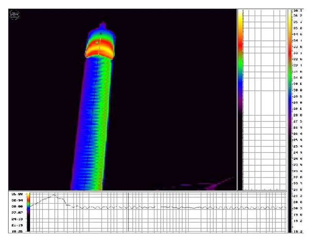
The diagnostics of bushings is conducted on the basis of the following measurements: dielectric losses coefficient tgδ in frequency range, thermovision analysis and oil DGA analysis.
Relation between water content in solid cellulose insulation and water dissolved in oil
Water content in cellulose (in %) plotted against water dissolved in oil (in ppm) at the same temperature. Useful conclusions can be derived from this graph. For instance, a sudden cooling (load drop) of the transformer with wet insulation may cause insulation breakdown, since the maximum content of water that can be dissolved in oil is exceeded and in water bubbles are formed in oil.
Cellulose structure
Cellulose fibers are composed of chain-forming molecules. Ageing breaks links between these molecules, and reduces length of cellulose fibers. Aged cellulose becomes brittle and looses its tensile strength. Cellulose reaches end of its technical life when its tensile strength is reduced by half.
Wet solid insulation vs. cellulose ageing process
High operating temperature and water content reduce the technical life of cellulose insulation. It's remaining technical life is reduced by half if the temperature increases by 6oC to 8oC. Assuming 0.5% moisture content in cellulose its technical life can be assessed at 500 years if the operating temperature is 80oC, but is reduced to 50 years at 100oC, to 6 years at 120oC, and to 1 year at 140oC.
Frequency Response Analysis
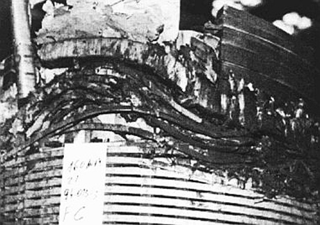
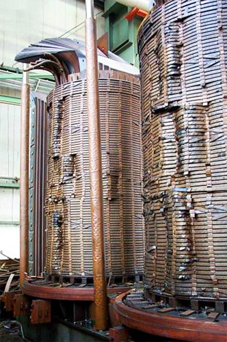
Typical buckling of coils due to the hoop-stress caused by short-circuit current, axial deformation of the upper coils and damage to the regulation winding.
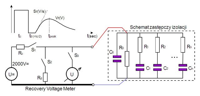
Equivalent circuit of the RVM instrument connected to the examined winding insulation. Charging voltage and the polarization recovery voltage form is presented schematically on the upper sketch.
The highest value of the polarization recovery voltage Vr plotted against the charging time T. Peak of this characteristic shifts to the shorter time T for a higher water content in the winding insulation.